What the 3dfier algorithm actually do to make 3D objects out of 2D polygons and point clouds? This page explains the steps implemented to create 3D models.
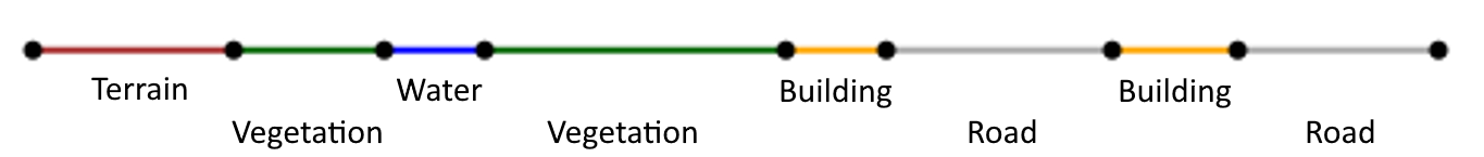
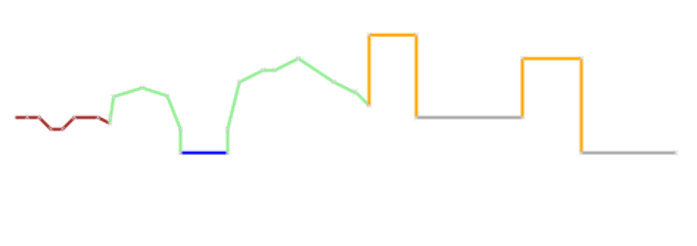
The input of the algorithm is a set of topologically connected polygons. An example is shown below from a horizontal point of view. All object belong to one of the 7 object classes supported by 3dfier;
- Terrain
- Forest
- Water
- Road
- Separation
- Building
- Bridge / Overpass
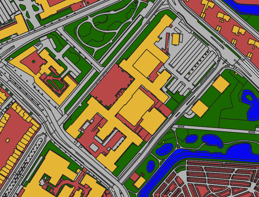
The objects when viewed in a GIS software using the same colors as in the horizontal view.
On top of the objects we drape the points read from a point cloud.
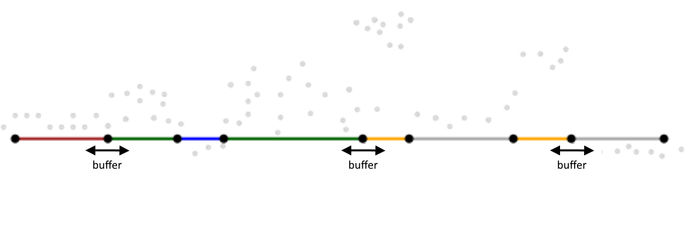
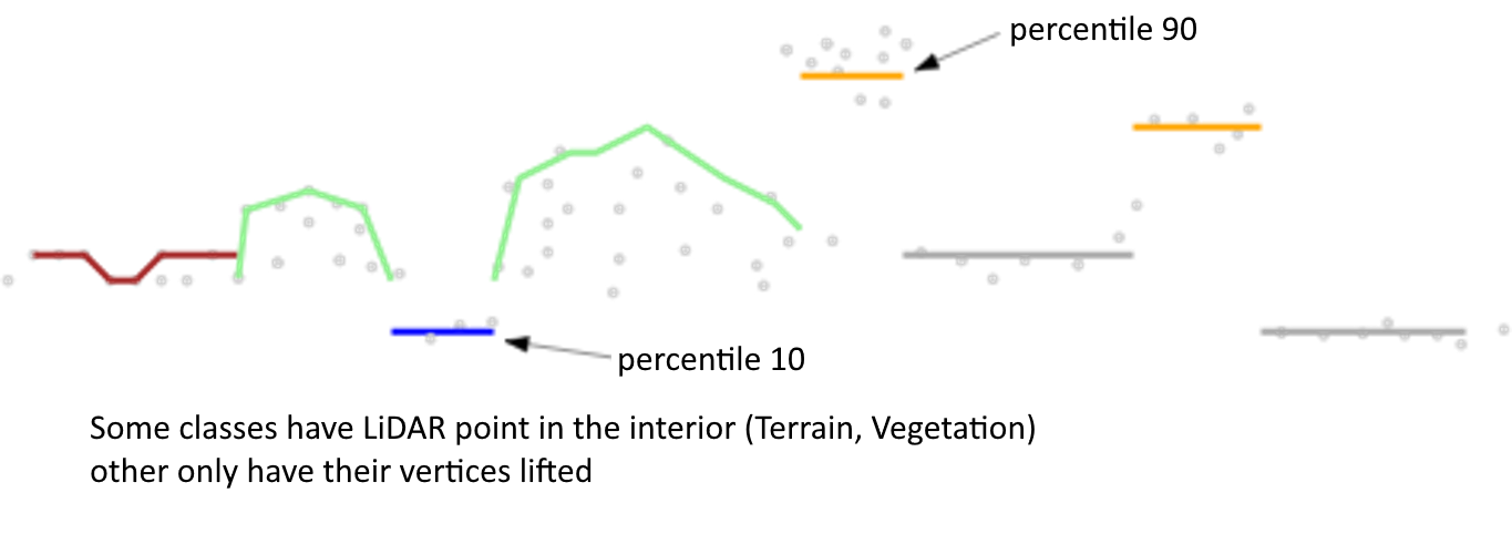
Using the points read from the point cloud we select all points within the 2D buffer distance of a vertex. The height is stored into a list of heights per vertex. In the configuration the lifting percentile per object type is stored. The type of the object is requested and using the percentile and all heights stored the height of the vertex for this object is calculated. This process is repeated for each vertex in the imported 2D polygons. To describe objects in the terrain and forest classes in a more realistic way additional height points are added within the 2D polygons. These additional height points represent better the height differences. This process is called lifting.
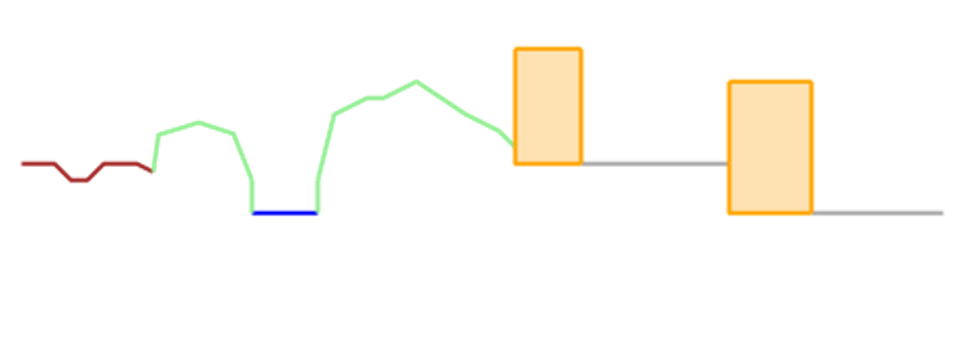
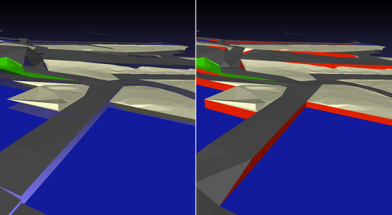
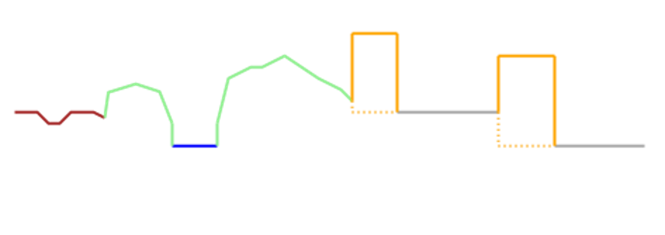
After lifting the polygons from 2D to 3D many connected polygons will have vertical height jumps. These height jumps are shown in the left side of the picture below where on the right side these are solved and vertical walls (red) are added. Since the goal of the algorithm is to create a watertight model we have to solve for these holes in the model. This is explained in the next step.
Now all polygons are lifted to height we will solve for the holes we created. Based on type of object we say it is soft or hard, the best description would be nature and man-made. Heights of soft features are allowed to be moved towards that of a hard feature. Also water objects are forced to stay flat and its heights will not be moved. The result of this process is a 3D topologically connected surface containing all 2D polygons as 3D objects as shown below. This process is called stitching.
From the created model there are two output options for buildings;
- Trianglated MultiSurfaces
- Solids
In the image below one can see MultiSurface output where the walls and roof of the building are stored in the object as a collection of triangles.
In the image below one can see buildings output as Solid objects where the walls and roof are stored as rectangular surfaces.