
In the lifting_options we define the settings used for lifting polygons of the specified class. In total there are 7 different possibilities to choose from;
- Building
- Terrain
- Forest
- Water
- Road
- Separation
- Bridge/Overpass
If a class is not defined the default values will be used. Default values can be found in resources/config_files/myconfig_DEFAULTS.yml.
Building
roof:
height: percentile-90 # Percentile of points within radius of building vertices for roof height lifting, building_radius_vertex_elevation is defined in options
use_LAS_classes: # LAS classes to be used for this class. If empty all classes are used
- 6
ground:
height: percentile-10 # Percentile of points within radius of building vertices for floor height lifting
use_LAS_classes:
- 2
- 9
lod: 1 # Define the Level Of Detail for Buildings (0 and 1 possible)
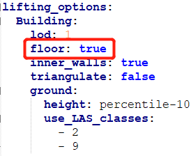
floor: true # Set if floors should be created
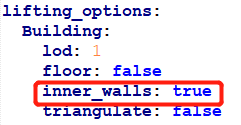
inner_walls: true # Set if the walls between to adjacent buildings within a block should be created
triangulate: false # Set if the output should be triangulated, only works for non-triangular output formats like CityGML/IMGeo
roof and ground settings
Settings within the roof section only apply to the calculation of the roof height where settings in the ground section apply to the calculation of the floor height.
height: percentile-xx
To define the height of an object calculated from the points close to it we use percentiles. The percentile defined here is a number between 0-100 written at the location of the xx e.g. percentile-10. The percentile is calculated from the heights of the points corresponding to the vertex of the object as described in output_options:radius_vertex_elevation. All heights are ordered and the value at the configured percentile is calculated.
Lets say we have a list of 10 height values and we configure a percentile of 90. We order the 10 height values from low to height and we will take the 9th value in the list. The 9th value because: 10 values * 90th percentile / 100 = 9.
Example;
Height values: 1-1-5-7-6-9-6-3-4-2
Configuration: percentile-50
Ordered height values: 1-1-2-3-4-5-6-6-7-9
Height calculated: 4
use_LAS_classes
This defines what LAS classes to use for the height calculation of its related object class. Only points classified with the LAS classes configured here are allowed to be added to the height lists of the vertices.
When points are read the algorithm checks:
- the classification of the point according to the input_elevation:omit_LAS_classes
- the classification of the points according to this list
- if the point is within distance set by output_options:radius_vertex_elevation
Lets say this setting corresponds to the class Road and the LAS classes configured are 2 (ground) and 11 (road surface). All points read that are within distance of the vertex of the road object and have LAS classification of 2 or 11 are added to the heights list of that vertex of the road object.
If no classes are defined here, all points read are used!
use_LAS_classes_within
Additional to the use_LAS_classes there is a more specific version that defines additionally that points have to lay within a polygon to be allowed to be added to the heights list. All 3 steps described in the previous setting are taken plus an additional one that checks if the point falls within the polygon. This can be used for example for objects that are influenced by surrounding objects and their heights like bridges crossing over bridges.
If use_LAS_classes are not defined but only use_LAS_classes_within, points within distance of a vertex but not within the polygon are not filtered by class and all classes are used!
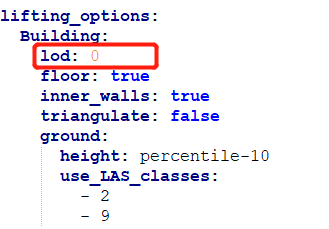
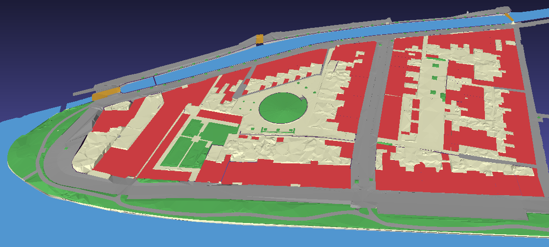
lod: 0
Create a building as a flat surface at ground level. The calculation of the floor height is done identical to LoD 1 and reconstructed with vertical walls from the terrain to the floor surface of the building. The vertical walls are added to make the model water tight and close the terrain surface.
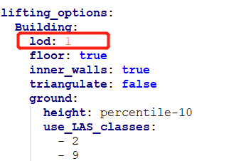
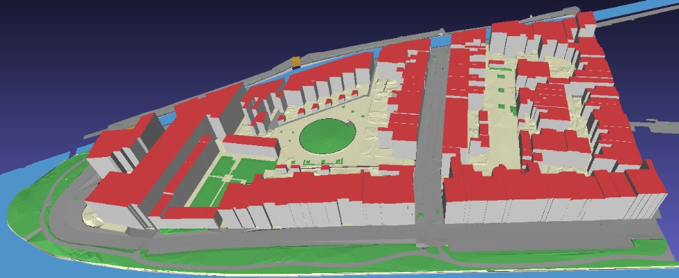
lod: 1
Create a building as an extrusion from the ground level to the roof level. The calculation of the floor height is done using the Building:ground:height percentile and the roof height using Building:roof:height percentile. When the heights are calculated the two surfaces, roof and floor, are built and calculation of the vertical walls is started. The walls are topologically noded to neighbouring buildings. If a building is taller then its neighbour an additional vertex is added at the roof height of its neighbour. Same holds for a buildings floor being lower then that of a neighbour.
For example we have two buildings with their floors at 0 meters and roofs at 10 and respectively 9 meters height. The building with the roof of 10 meters will contain three vertices at the connecting wall segment, at 0, 9 and 10 meters. The building with the roof of 9 meters will contain two vertices at the connecting wall segment, at 0 and 9 meters. This way we can assure the model to be both watertight and topologically correct.
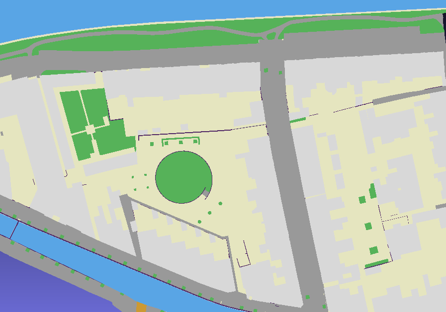
floor: true
Reconstruct polygons of the floor of buildings. When set to true (and configuration set to lod: 1) the model will create a watertight 3D solid object per building.
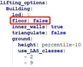
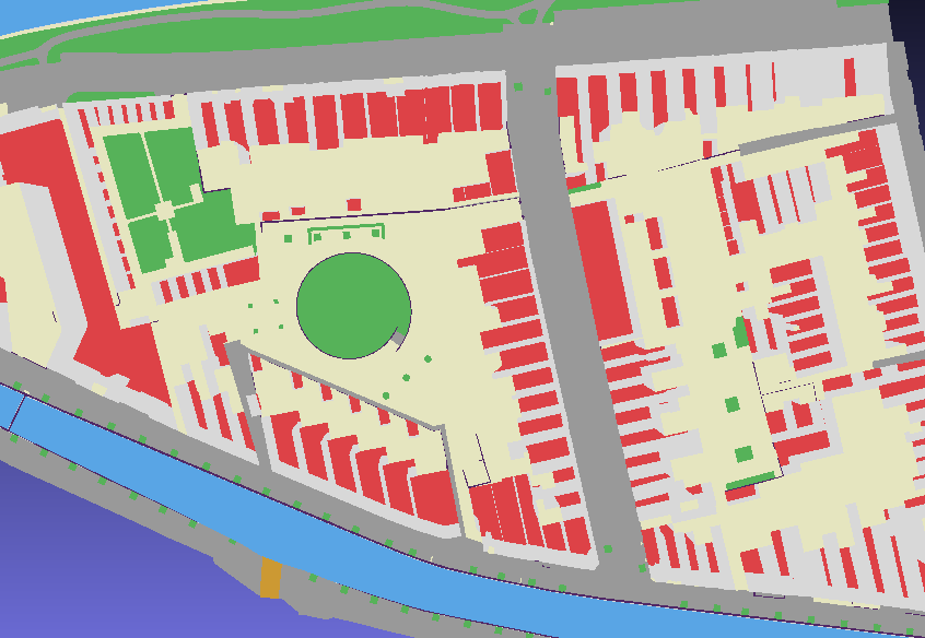
floor: false
Do not reconstruct polygons of the floor of buildings. The buildings are still connected to the surrounding objects through the walls but do not contain polygons for the floors.
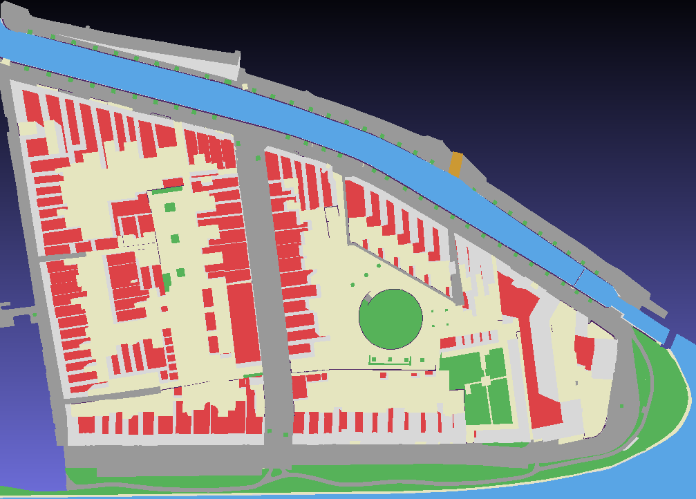
inner_walls: true
Reconstruct polygons for walls in between connected buildings. When set to true (and configuration set to lod: 1) the model will create walls in between houses that are connected with at least one side.
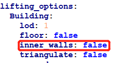
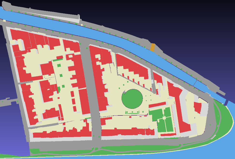
inner_walls: false
Do not reconstruct polygons for walls in between connected buildings.
triangulate: true
Create multisurface geometry for buildings by triangulating polygons. This is the default for output formats that don’t support solids or only support multipolygon geometries.
triangulate: false
Create solid geometry for buildings, only works when an output format supports solid geometries.
Water
height: percentile-10     # Percentile of points within radius of water vertices for lifting, radius_vertex_elevation is defined in options
use_LAS_classes:          # LAS classes to be used for this class, if empty all classes are used
  - 2
use_LAS_classes_within:   # LAS classes to be used for this class, but only if points fall within the polygon and the range of the vertex
  - 9
Class for objects that describe water surfaces. Water objects will be raised to a single height since water is expected to be flat.
Road
height: percentile-50
filter_outliers: true     # Filter outliers by iterative Least Squares fitting of 3D quadric surface, only replace heights of detected outliers
flatten: true             # Filter outliers by iterative Least Squares fitting of 3D quadric surface, replace all heights of polygon with the fitted plane which results in smoother roads
max_outlier_fraction: 0.2 # Cancel outlier filtering in case the fraction of outliers is higher that this value
use_LAS_classes:          # LAS classes to be used for this class, if empty all classes are used
  - 2
  - 11
Class for objects that describe road surfaces. For road object each vertex will be raised to the height calculated by the points that correspond to the vertex. Extra options are available to remove outliers within road objects to overcome unwanted features.
filter_outliers: true
Option to clean road polygons that contain spikes due to used height points. The filter implemented is an iterative Least Squares fitting of a 3D quadratic surface. The input are the polygon vertices with their calculated heights based on the percentile. A minimum of 6 vertices is needed for the filter to work. The filter fits a surface and finds the largest outlier. When the outlier is smaller then 2 sigma of the standard deviation iteration will stop.
All heights of vertices which are marked as an outlier are replaced with the value represented by the fitted surface. See flatten for further replacement of height values.
Important: not all height points are used for performance reasons, only vertices. Therefore this filter is extremely sensitive to the arrangement of vertices of the road polygon
filter_outliers: false
Disable filtering of outliers using iterative Least Squares fitting of a 3D quadratic surface.
flatten: true
Option to even further fit the road objects towards the quadratic surface calculated by filter_outliers. By enabling this all heights of the polygon vertices are replaced by the values represented by the fitted surface.
flatten: false
Disable height replacement of vertices not marked as outliers by the Least Squares 3D quadratic surface fitting in filter_outliers.
Separation
height: percentile-80
Class that describes objects inspired by objects contained in the Dutch BGT. These objects generally describe walls or wall-like objects with a flat top.
Bridge/Overpass
height: percentile-50
flatten: true             # Filter outliers by iterative Least Squares fitting of 3D quadric surface, replace all heights of polygon with the fitted plane which results in smoother bridges
max_outlier_fraction: 0.2 # Cancel outlier filtering in case the fraction of outliers is higher that this value
Settings for reconstruction of bridges is handled in this class. Some of the sides of a bridge must be floating with no connection to neighbouring polygons and some of the sides need to be stitched to the neighbours. A rather complex method is used to identify what vertices to stitch to adjacent objects and what vertices to skip so they ‘float’.
The Least Squares 3D quadratic surface fitting as described in road:filter_outliers is always applied.
flatten: true
See road:flatten: true for more information. This adjusts all vertices of the bridge to the height of the fitted quadratic surface.
flatten: false
See road:flatten: false for more information.
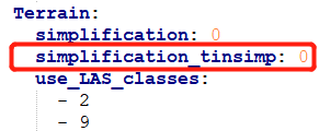
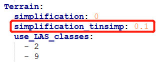
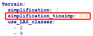
Terrain
simplification: 0 # Simplification factor for points added within terrain polygons, points are added random
simplification_tinsimp: 0.1 # Simplification threshold for points added within terrain polygons, points are removed from triangulation until specified error threshold value is reached
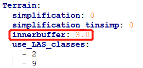
innerbuffer: 0.0 # Inner buffer in meters where no additional points will be added within boundary of the terrain polygon
Since it is a special case the Terrain class is adding raw points from the point cloud to the interior of the polygon. Since a terrain polygon can be rather large and contains information about relief within its boundaries more information is needed.
Point clouds normally contain a lot of information. Since we don’t want the 3D model to contain lots of unnecessary information, we introduce simplification algorithms. These algorithms make sure only a selection of points from the point cloud are added to the interior of terrain polygons.
simplification
Random filtering using a uniform integer distribution between 1 and supplied simplification value. A value of 6 generated equal changes compared to throwing a 6-sided dice.
Usage of simplification_tinsimp is preferred, this is just a cheap alternative.
Don’t use simplification and simplification_tinsimp in the same configuration!
simplification_tinsimp
For simplification of terrain there is an algorithm implemented that describes the terrain with as little triangles as possible. It minimises the amount of triangles while it makes sure the set maximum error is not exceeded. Points that do not add more detail to the terrain when added are not used. The minimum detail it needs to add must be higher then the configured simplification distance. The algorithm is based on the paper of Heckbert, P. S., & Garland, M. (1997). Survey of polygonal surface simplification algorithms. It uses Greedy Insertion to add points in a specific order to the triangle mesh so the point with the largest impact on the terrain is processed first. The points are added iteratively up-to the point the calculated error is less then the configured threshold.
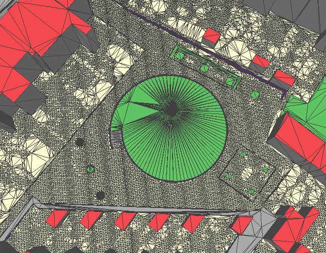
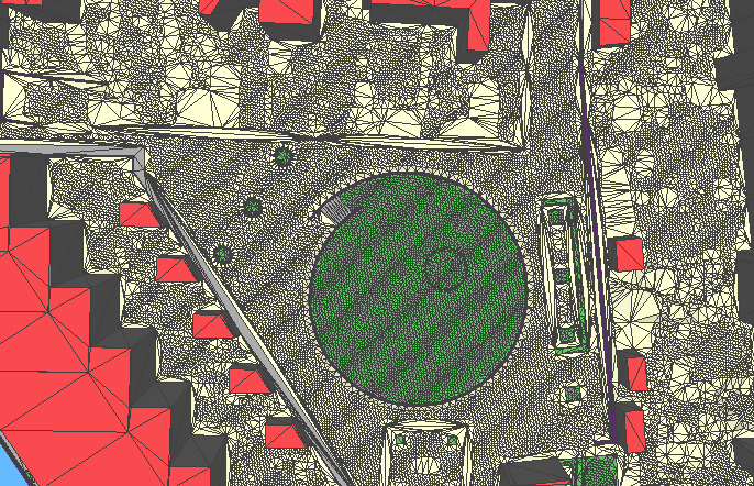
Below are three examples of the impact of this simplification setting.
- The first is 0.0 meters which results in all height points within the terrain polygon to be added. It results in a lot of triangles in the yellow terrain polygons.
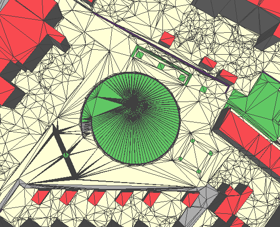
- The second is 0.1 meters where it means that the terrain TIN is allowed to have a maximum deviation of 0.1 meters with the point cloud. The result shows a lot less triangles compared to the first example. In area’s with a bit more relief close to the buildings there are quite some triangles left.
- The final example is 0.5 meters an it results in only points added at locations that greatly influence the height of terrain since the example area is quite flat.
Download YAML and OBJ of simplification_tinsimp:0
Download YAML and OBJ of simplification_tinsimp:0.1
Download YAML and OBJ of simplification_tinsimp:0.5

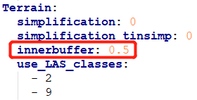
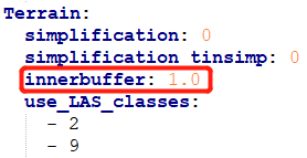
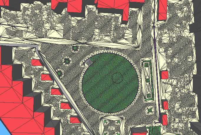
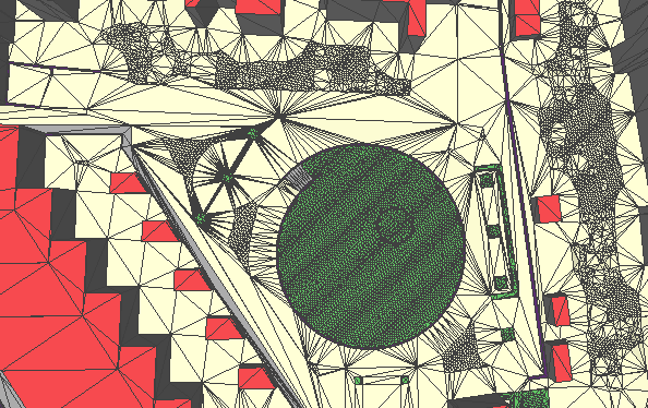
innerbuffer
In case there is a need to prevent points to be added close to polygon boundaries there is the innerbuffer setting. When this is used the interior points are only added when the distance to the boundary is a minimum of the supplied value in meters. Below are three examples that show what happens when setting and increasing the innerbuffer value.
Forest
simplification: 0            # Simplification factor for points added within forest polygons, points are added random
simplification_tinsimp: 0.1  # Simplification threshold for points added within forest polygons, points are removed from triangulation until specified error threshold value is reached
innerbuffer: 0.0             # Inner buffer in meters where no additional points will be added within boundary of the forest polygon
All options available for Terrain are also available for the Forest class.
There is no proper solution yet on how to nicely represent vegetation. Therefore in general configurations with only ground points are used for the Forest class.